The effect of slipper-piston clearance on hydraulic pumps

In a swashplate piston pump, the "piston assembly" consists of a piston rod with a ball head at the front end and a brass slipper with a ball socket. These two components are mechanically hinged together to form a ball-and-shoe joint with a standard clearance of 0.008~0.016mm. The maximum allowable clearance is 0.3mm. This standard can be found in early Rexroth piston pump repair manuals. However, current Kawasaki piston pump repair manuals state that if the clearance between the piston ball head and the slipper ball socket exceeds 0.3mm, the piston needs to be replaced.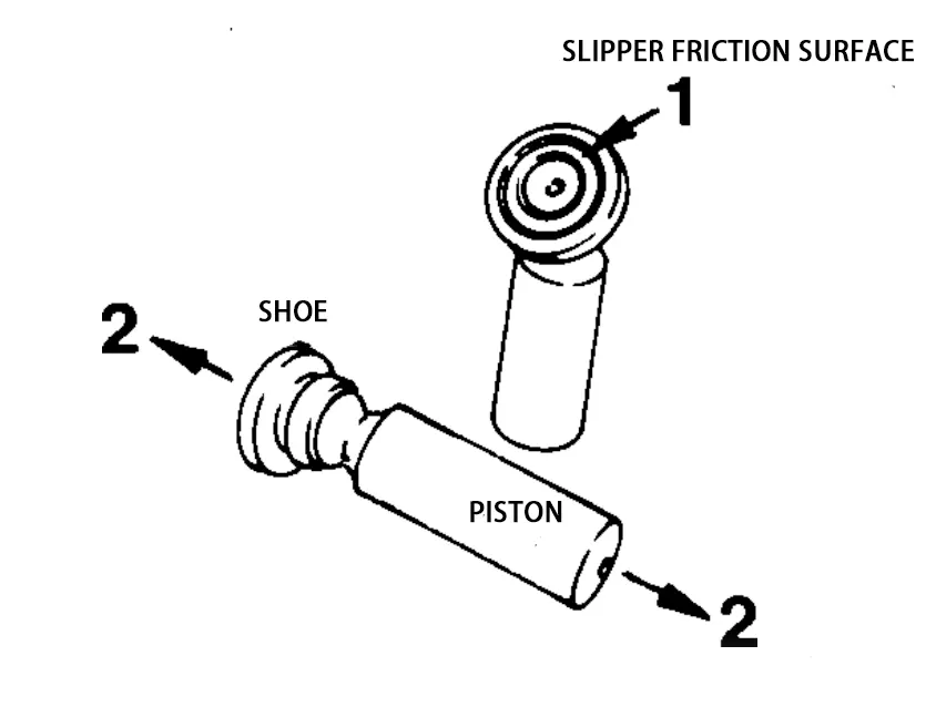
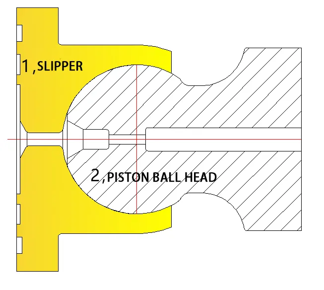
What are the consequences if the clearance between the plunger ball head and the slipper ball socket exceeds 0.3mm and a new plunger is not replaced? Theoretically, the pump's displacement will decrease. For example, with a clearance of 0.3mm, the pump's maximum flow rate will decrease by 2.5%. However, in reality, during plunger pump maintenance, many disassembled pumps show clearances between the plunger ball head and slipper ball socket far exceeding 0.3mm. This not only leads to flow loss but also causes a series of problems, including:
When the swashplate squeezes the slipper and plunger during the downward stroke in the cylinder bore, some of the compressed oil will overflow from the clearance between the plunger ball head and slipper, reducing the thickness of the hydrostatic oil film on the slipper. This causes contact friction and wear between the slipper and the swashplate, shortening the pump's service life.
As the clearance between the slipper and the piston ball head increases, the pump flow pulsation value also increases.
Increased internal leakage leads to higher casing pressure, higher oil temperature, and increased noise.
Reduced oil supply to actuators in the hydraulic system causes slower operation.
With accumulated pump usage time, the clearance between the slipper and piston ball head increases more rapidly, eventually leading to slipper slippage.
The overall efficiency of the piston pump decreases as the clearance increases.
In swashplate piston pumps, the piston suction process involves the return disc lifting the slipper, which in turn lifts the piston body. During application, a gap arises at the joint between the piston ball head and the slipper, a problem that plagues piston pump manufacturers worldwide. The rigidity and coefficient of friction of the slipper material are often contradictory and irreconcilable. To solve this problem, hydraulic scientists around the world have racked their brains, exploring various methods. These have resulted in a wide variety of slippers, including graphene-coated slippers, slippers with micro-pitted surfaces on the slipper support ring, bimetallic slippers, all-steel slippers, inverted pistons (Linde pump inverted pistons), new materials such as 3D-printed super-strong metal forming a honeycomb mesh support (3D-printed sponge-like microporous structure) with excellent friction coefficient soft copper material melted into the micropores, and high-strength slippers using new technologies.
The open hydraulic system developed by hydraulic professors at Yanshan University uses a closed-loop pressurized oil supply method for its piston pump. Denison of France took a more radical approach, directly modifying the pump housing, increasing the suction port diameter, and incorporating an internal gradient flow channel. The aim of both methods is to increase the head pressure, raise the absolute pressure in the S-pipe, and increase the oil supply pressure at the bottom of the piston. This allows the pressurized oil to drive the piston back, eliminating the negative pressure of the self-priming oil and reducing the force required for the return plate to pull the slipper back on the piston. The goal is to eliminate the gap between the piston ball head and the slipper ball socket. The image below shows the gap between the piston and slipper, and the marks left by the slipper striking the swashplate friction surface.
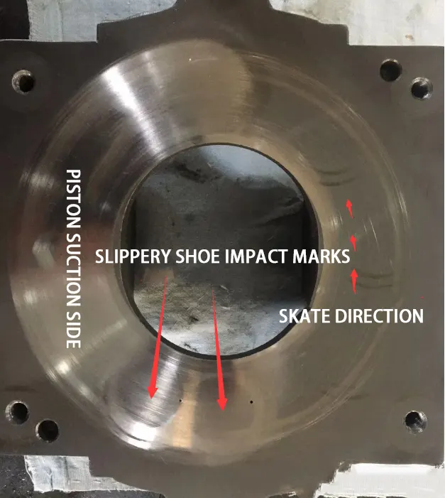
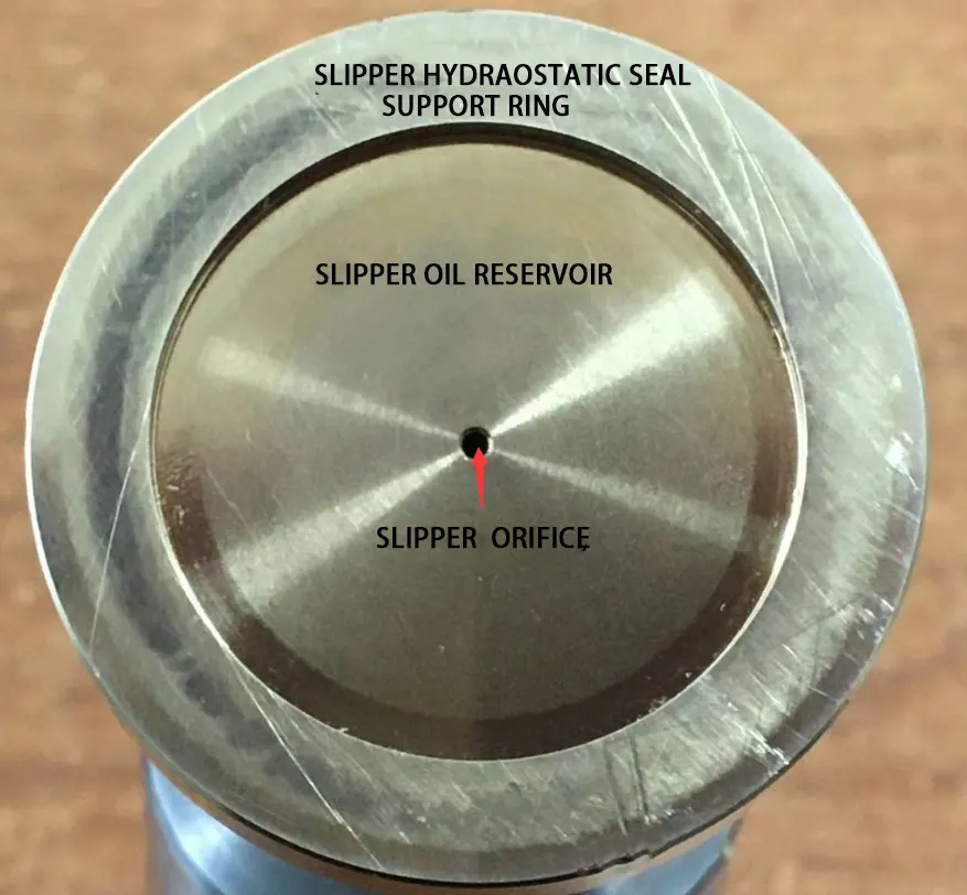
This article explains how the slipper strikes the swashplate surface and leaves impact marks: When there is a certain clearance between the slipper and the plunger, when one of the plungers pressurizes the oil in the cylinder bore to the bottom dead center, some of the high-pressure oil remaining in the closed volume chamber of the cylinder bore is sealed inside. This cylinder bore, which seals the high-pressure oil, rotates to the oil suction window of the distributor plate. As it rotates past the pressure relief hole on the distributor plate, the high-pressure oil sealed in the cylinder bore is released into the hole. The oil in the sealed chamber of the cylinder bore changes from pressurized to depressurized and then rotates into the edge of the distributor window, preparing to open the plunger's upward stroke. During the oil suction process, the return plate pulls the slipper upwards. While the slipper moves upwards, the plunger does not follow. This is because the gap between the slipper and the plunger ball head changes from a tight to a separated state. Only after the slipper's upward pulling stroke exceeds the gap does it pull the plunger ball head, causing the plunger body to move upwards. When the plunger in the cylinder bore rapidly moves upwards to draw in oil, the cylinder bore's volumetric cavity is large but the opening is small, preventing timely replenishment of oil. This creates negative pressure within the cylinder block's distribution window, generating a pulling force on the plunger body and, in turn, a pulling force on the slipper, bringing the slipper and plunger ball head to their maximum gap state.
When the return plate pulls the slipper, causing the plunger to reach top dead center, the cylinder block plunger cavity is filled with unpressurized oil. When the cylinder block's waist-shaped distribution window rotates into the triangular flushing groove in front of the high-pressure window's R-shape on the distribution plate, the high-pressure oil in the high-pressure zone of the distribution plate rushes into the cylinder block plunger cavity through the triangular groove. This causes the pressure inside the cylinder block plunger cavity to instantly change from low pressure to the same pressure value as the high-pressure window on the distribution plate. It is this instantaneous rush of pressurized oil that impacts the plunger body. Driven by this instantaneous pressure, the plunger body juts upwards, the ball head crossing the clearance area and striking the slipper, leaving impact marks on the swashplate surface.
This process repeats continuously, causing cumulative fatigue loss to the ball socket, deformation of the soft ball socket, and a continuous increase in clearance and leakage. The offsetting gap created by the slipper lifting the plunger and the slipper pressing the plunger once shortens the plunger stroke, reducing the pump's displacement. When this gap reaches 1mm, the pump's displacement decreases by 8.3%; when the gap reaches 2mm, the pump's displacement decreases by 16.6%.
The image of the swashplate friction surface shows two impact marks, one on the right and one on the left. These are the impact marks on the swashplate before and after the step jump, at the minimum and maximum angles.
Without disassembling the plunger pump, how can one determine online whether a gap has formed between the plunger and the slipper? Several methods are as follows:
1. Use a pressure sensor to detect the pressure value curve at the plunger pump outlet. A normal pump's pressure curve is a smooth straight line. If a gap has formed between the plunger and the slipper, the pressure curve detected by the sensor will show a jagged, serrated curve resembling a knife edge.
2. Testing methods using human sensory perception: ① Touch the pump housing with a screwdriver and listen; you will hear a regular clicking sound. ② Hold the pump outlet hose; when the pump is in the low-pressure, high-flow range, you will feel a slight vibration and a tingling sensation in your hand. ③ Use a stopwatch to measure the operating speed of the actuator; compare the calculated theoretical speed with the actual measured speed. Methods to avoid or reduce the gap between the slipper ball joint and the plunger ball head in hydraulic systems using piston pumps: ① Increase the liquid level, allowing oil to backflow into the pump suction pipe. ② Increase the diameter of the oil tank outlet and equip it with a corresponding disc valve to maximize the head pressure. ③ The distance between the oil tank and the pump should be as short as possible; the maximum distance should not exceed 0.8 meters, and there should not be more than two bends in the pipe. ④ The pump suction pipe should be 1.2 to 1.5 times larger than the diameter of the S-port on the pump housing. ⑤ Multiple pumps should not share a single pipe unless you have a special method to ensure that the absolute pressure at the suction port of each pump is above 1.0 bar.
-----------------This article is excerpted from the work of hydraulic repair expert Ma Mingdong.
Tags: Axial Piston Pump, Piston Ball Head, Slipper Ball Socket, Ball Joint Clearance, Swashplate, Internal Leakage, Flow Pulsation, Hydrostatic Oil Film, Pump Overhaul, Volumetric Displacement