How can the case leakage of pumps and motors be measured in a closed-loop system?

Let's analyze an issue concerning case flow in pumps and motors within a closed-loop system.
When working with closed-loop hydraulic systems, it is often necessary to monitor the case pressure and flow rate of the hydraulic pump and motor to assess their condition and check for wear. A client recently installed a closed-loop system and decided to perform such a check by installing a flow meter at the case drain port of the closed-loop pump. However, they observed that even when the motor displacement was adjusted to zero, the flow rate at the pump’s case drain port remained roughly equal to the output flow of the charge pump. Is this level of case leakage considered normal, and does it indicate that the pump or motor is faulty?
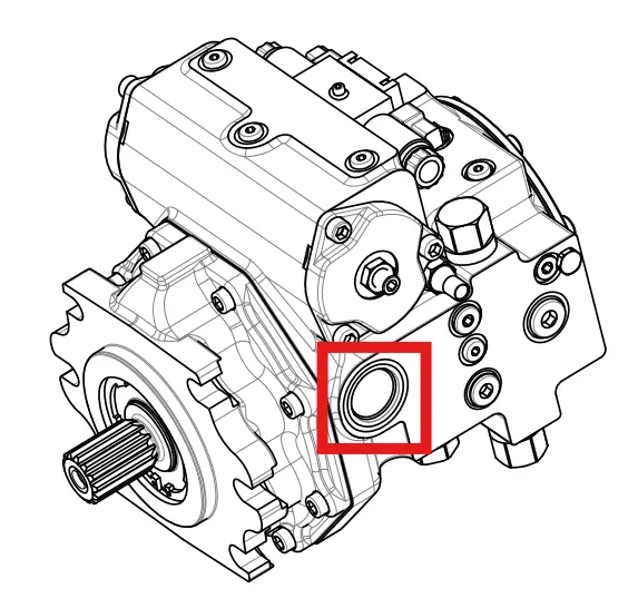
Diagram showing the location of the housing drain port
I. Closed-system structure
Before answering this question, let us first review the fundamentals of a closed-loop system. Also referred to as a hydrostatic transmission, a closed-loop system consists of a variable-displacement pump and either a fixed- or variable-displacement motor, operating together within a closed circuit. In this configuration, fluid exiting the motor does not return to the reservoir; instead, it flows directly back to the pump’s inlet. The flow output from the pump is not only variable in volume, but its direction can also be reversed by shifting the internal swashplate across the neutral (center) position. Consequently, the direction and speed of the motor’s rotation can be controlled by adjusting the pump itself, thereby eliminating the need for the directional and flow (speed) control valves typically required in an open-loop system.
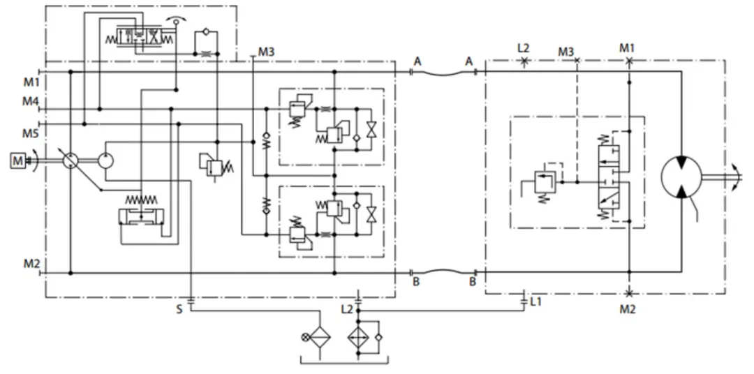
Schematic diagram of the basic principles of a closed system
II. Components of the Charge Pump
Due to internal leakage within closed-loop hydraulic pumps and motors—which causes fluid to escape the transmission circuit and return to the reservoir—a charge pump (or make-up pump) is required to replenish the system and ensure the circuit remains fully primed with fluid during operation. The charge pump is typically mounted behind the main closed-loop pump, though it may also be configured as a separate unit within the system. As a general rule of thumb, the charge pump’s flow rate is approximately 20% of the main pump’s output flow, or 10% of the combined flow of the pump and motor; this capacity may be increased if the system experiences higher leakage or operates at elevated temperatures.
In practical applications, the outlet pressure of the charge pump is typically set between 18 and 36 bar, with the exact value depending on the manufacturer’s specifications and the customer’s requirements. A standard charge circuit consists of a charge pump, a charge relief valve, and two charge check valves; these components work together to allow the charge pump to replenish fluid in the closed-loop circuit. Once the circuit pressure reaches the setting of the charge relief valve, the excess flow from the charge pump is directed through the relief valve, passing through the pump housing, the motor housing—or both—before returning to the reservoir.
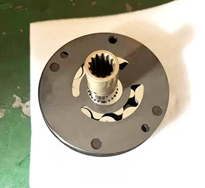
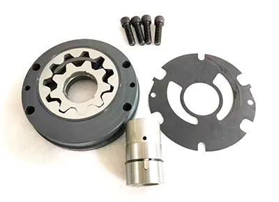
Exploded view of the charge pump components
III. The function of measuring the case drain flow rate
When a pump or motor becomes worn or damaged, internal leakage increases, thereby reducing the flow available for performing useful work. Consequently, the condition of a pump or motor can be assessed by measuring the flow rate within its case drain line (i.e., the internal leakage) and comparing this value—expressed as a percentage—against the theoretical or design flow rate.
In open-circuit hydraulic systems, it is common practice to monitor the case pressure and leakage of a pump or motor. In the field, when equipment lacks sufficient power and a hydraulic pump is suspected as the cause, operators sometimes remove the case pressure plug to observe the resulting oil spray; they then estimate the leakage volume—and thus the extent of wear—based on the height and rate of the oil flow. However, this method is hazardous and results in the waste of hydraulic fluid; therefore, it is not recommended. A more professional and appropriate approach is to connect a flow meter to measure the actual leakage flow.
IV. Specifics of Case Drain in Closed-Type Housings
When measuring the case drain flow of a hydrostatic transmission, the flow from the charge pump must be taken into account. In most closed-loop systems, the charge pump’s relief valve discharges fluid into the pump or motor housing. Depending on the specific setup, the case drain lines from the pump and motor may be routed back to the reservoir either separately or combined into a single return line.
Returning to our specific case: if the hydraulic motor’s case drain line is connected to the pump housing—with the fluid subsequently flowing from the pump housing back to the reservoir—the flow meter installed on the pump’s case drain line will likely show a reading approximately equal to the total flow of the charge pump. Here is why: suppose the charge pump provides a flow of 11 L/min. Of this, 4 L/min leaks out of the circuit through the motor (via its case drain), and 3 L/min leaks out through the pump. What happens to the remaining 4 L/min? It must go somewhere—it cannot simply vanish. Consequently, the charge relief valve opens to divert this 4 L/min; however, this fluid is ultimately directed into either the pump or motor housing.
Therefore, if the motor’s case drain line is routed through the pump housing back to the reservoir, the flow meter on the pump’s case drain line will register a total flow—in this example, 11 L/min—representing the sum of these individual leakage and relief flows. This is considered normal operation. If the reading deviates significantly, it may indicate that the internal leakage within the pump is excessive.
V. Conclusion
If you wish to monitor the case leakage of a pump or motor in a closed-loop system individually, you must first determine which component’s housing (the pump’s or the motor’s) receives the discharge from the charge-circuit relief valve. Ideally, the case drain lines from both the pump and the motor should be routed back to the hydraulic reservoir independently. If you cannot identify which housing receives the charge-relief flow, you will be unable to distinguish between leakage originating internally within a component and flow arriving from an external source; consequently, you cannot accurately assess the component's operating condition. For instance, if the charge-relief flow is directed into the pump housing, measuring the motor’s case drain flow will reveal the motor’s condition, but not the pump’s. Conversely, if the charge-relief flow is directed into the motor housing, measuring the pump’s case drain flow will reveal the pump’s condition, but not the motor’s. While it is technically possible to reroute the charge-relief flow into a separate return line during testing, doing so is typically quite cumbersome.
Some might argue that an exact flow value is unnecessary—that continuous monitoring is sufficient. For example, if the initial flow rate is 11 L/min, one could use this as a baseline; if the flow were to suddenly increase—say, to 20–30 L/min—it would clearly indicate a system fault. While this approach may not pinpoint whether the issue lies with the pump or the motor, it is certainly a valid and effective diagnostic strategy. In fact, many predictive maintenance systems for hydraulic pumps operate on this very principle.
Ultimately, attempting to assess the condition of a pump or motor in a hydrostatic transmission based on case drain flow—without a complete understanding of the closed-loop circuit configuration—can lead to erroneous conclusions. This may result in the unnecessary replacement of functional components, causing avoidable waste.
